

User manual
P331-2 setESD pulse injection IEC 61000-4-2
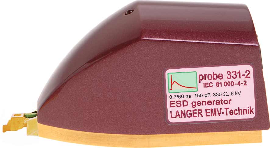
1 P331-2 ESD generator (IEC 61000-4-2)
The probe is used to generate standard ESD pulses according to IEC 61000-4-2 for ESD injection into the device under test via conductors (Figure 2).
The P331-2 probe allows the user to couple ESD into IC pins via conductors according to the standard IEC 61000-4-2 both directly and indirectly via coupling networks (standard). Coupling networks are used for coupling into interface connections or special high speed interfaces such as USB, LVDS, Ethernet, etc. Inductive or capacitive couplers are suitable coupling networks (Information: Langer EMV-Technik GmbH).
The P331-2 probe can only be operated in conjunction with the BPS 203 burst power station!
 | The probe is under high voltage during operation! Do not touch the tip! |
1.1 Design and function of the P331-2 probe
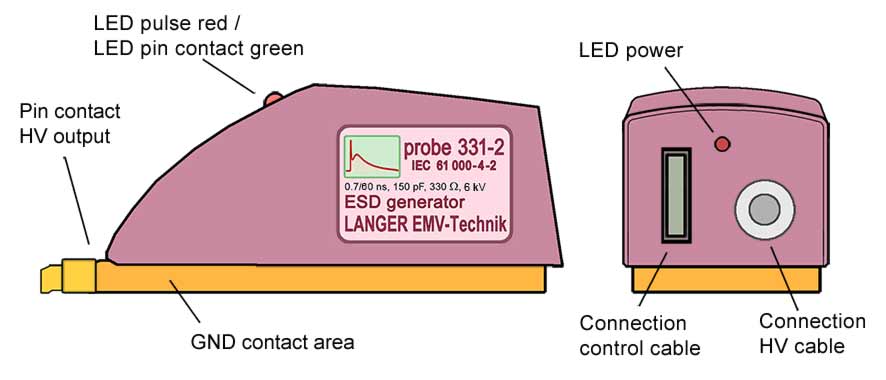
The pin contact is the P331-2's high voltage (HV) output that is used to inject the ESD pulse into the test IC.
The test pulse is generated in the probe through a high voltage switch and the coupling networks that are required by the standard (Figure 2). The high voltage that is needed for the pulse generation is generated in the BPS 203 and led to the HV port of the P331-2 probe via a high-voltage cable. The BPS 203 controls the P331-2. The signals are led to the control cable port via a control cable. The Pulse/Contact LED indicates when an ESD pulse is triggered and the device under test is contacted. The LED lights up green as soon as there is a galvanic connection between the pin contact and the device under test. A red light signals the triggered pulses.
The Power LED signals the P331-2's power supply. The probe's GND contact surface ensures low impedance, all-over contact with the GND 25 ground plane. Magnets that are integrated in the probe hold it on the ground plane.
1.2 Characteristics
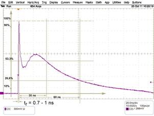
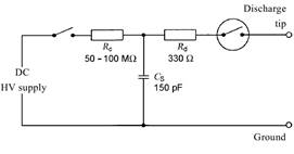
The ESD pulse is characterised by its current characteristic which is shown in Figure 2 shows the P331-2's equivalent circuit diagram. Both are in accordance with the standard IEC 64000-4-2. Please refer to Table 1 for the respective waveform parameters.
| HV [kV] | I max [A]+/- 10% | I (30 ns) [A]+/- 30% | I (60 ns) [A]+/- 30% |
|---|---|---|---|
| 0.5 | 1.86 | 1 | 0.5 |
| 1 | 3.73 | 2 | 1 |
| 2 | 7.5 | 4 | 2 |
| 4 | 15 | 8 | 4 |
| 6 | 22.5 | 12 | 6 |
| 8 | 30 | 16 | 8 |
| 9.5 | 36.8 | 20 | 10 |
| Table 1 Waveform parameters | |||
The respective short-circuit peak current can be calculated on the basis of the generator voltage UVG when the probe is used.
IP = UVG * K
where: K = 3.9 A / kV.
The equation reveals that the probe supplies 3.9 A per kV of the generator voltage.
Note:
The pulse form is only guaranteed if the P331-2 probe is operated at a minimum voltage of 200 Volt.
1.3 System set-up
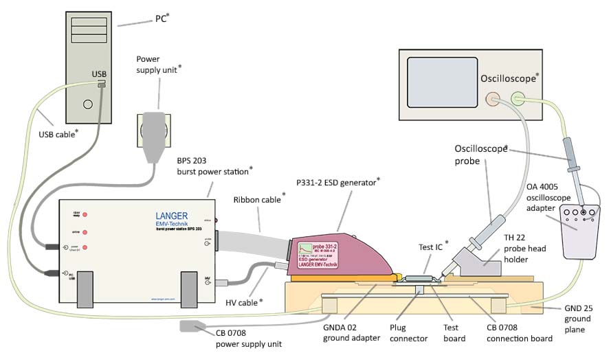
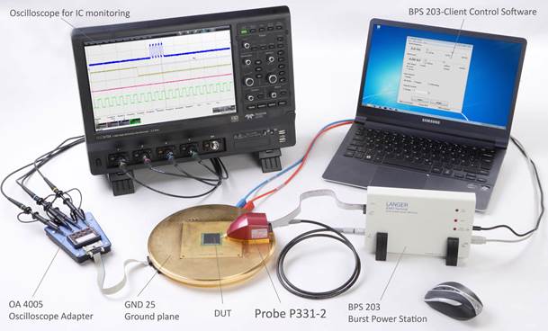
Figure 4 shows the set-up of the IC test system with the ICE1 test environment (Table 2) and the P331-2 probe set. The BPS 203 generates a high voltage and supplies this to the P331-2's HV input via the HV FI FI 1 m HV cable. In addition, the BPS 203 also controls the P331-2 via the ribbon cable. The PC in turn controls the BPS 203 via the USB connection. The BPS 203 client software is installed on the PC.
The ESD current pulse is generated from the high voltage in the P331-2 probe (equivalent circuit diagram Figure 3). The current pulse (Figure 2) flows into the test IC when contact is made to the pin.
The test IC is mounted on a test board. The test board is inserted into the ground plane and connected to the connection board via a plug connector.
The ground plane and the connection board are integral parts of the ICE1 IC test environment. The evaluation of signals from the test IC may require external devices such as an oscilloscope or special test hardware (Figure 5).
The devices listed in the table are described in their respective operating instructions:
| Task | Operating instructions |
|---|---|
| Guide line IC EFT immunity (Langer EMV-Technik GmbH) |
| ICE1 user manual |
1.4 Verifying the waveform
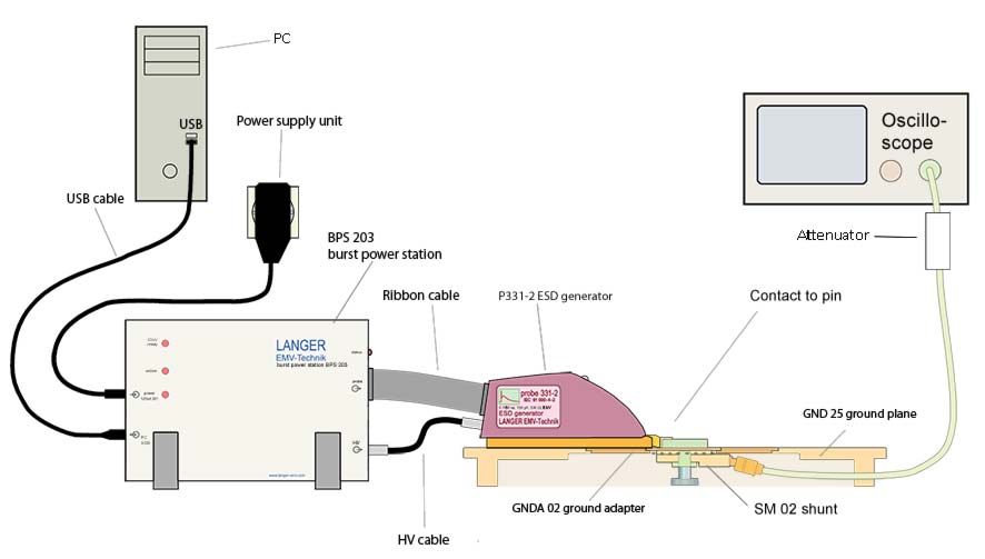
The SM 02-01 shunt can be used to verify the waveform of the current pulse. The shunt has a bandwidth of 3 GHz and can be loaded with a maximum pulse current of 180 A in the single-pulse mode.
The shunt is inserted into the GNDA 02 ground adapter (Figure 6). The SMA output is connected to the 50R input of an oscilloscope with a corresponding bandwidth. The oscilloscope's attenuator is set to 26 dB (x20). 1 V at the display corresponds to a current of 1 A in the probe. When using an oscilloscope with a bandwidth > 3 GHz, please note that this is limited to 3 GHz.
The waveform has to be verified prior to every major measuring job. Provided the waveform does not deviate from the given parameters, the P331-2 probe only has to be calibrated every two years by Langer EMV-Technik GmbH.
2 Safety instructions
When using a product from Langer EMV Technik GmbH, please observe the following safety instructions to protect yourself from electric shocks or the risk of injuries.
The device may only be used by personnel who are qualified in the field of EMC and who are fit to work under the influence of disturbance voltages and (electric and magnetic) burst fields.
Read and follow the user manual and keep them in a safe place for later consultation.
- Never use any damaged or defective devices.
- Carry out a visual check before using a measurement set-up with a Langer EMV-Technik GmbH product. Replace any damaged connecting cables before starting the product.
- Never leave a Langer EMV-Technik GmbH product unattended whilst this is in operation.
- The Langer EMV-Technik GmbH product may only be used for its intended purpose. Any other use is prohibited.
- Observe the operating and safety instructions for all devices used in the set-up.
- People with a pace-maker are not permitted to work with this device.
- The test set-up should always be operated via a filtered power supply.
- Attention! Functional near fields and interference emissions may occur when operating EMC test set-ups. The user is responsible for taking measures to prevent any interference to the correct function of products outside the EMC environment of the test set-up (in particular through radiated interference). This can be achieved by:
- observing an appropriate safety distance,
- use of shielded or shielding rooms
- The disturbances that are injected into the ICs can destroy (latch-up) the device under test if their intensity is too high. Protect the device under test by:
- increasing the disturbance gradually and stopping when a functional fault occurs,
- interrupting the power supply to the device under test in the event of a latch-up.
Attention! Make sure that internal functional faults are visible from outside. The device under test may be destroyed due to an increase in the injection intensity if the faults are not visible outside. Take the following measures as necessary:
- monitoring of representative signals in the device under test,
- special test software,
- visible reaction of the device under test to inputs (reaction test of the device under test).
We cannot assume any liability for the destruction of devices under test!
3 Warranty
Langer EMV-Technik GmbH will remedy any fault due to defective material or defective manufacture, either by repair or by delivery of spare parts, during the statutory warranty period.
This warranty is only granted on condition that:
- the information and instructions in the user manual have been observed.
The warranty will be forfeited if:
- an unauthorized repair is performed on the product,
- the product is modified,
- the product is not used according to its intended purpose.
4 Technical specifications
| P331-2 - ESD generator (IEC 61000-4-2) | |
|---|---|
| Dimensions (width/height/depth) | 79/41/40 (mm) |
| Weight | 0.25 kg |
| Frequency range: | 0.1 Hz – 10 Hz |
| Voltage range | 100 V - 9.5 kV |
| Pulse form | 0.7 / 60 ns |
| Energy storage capacity | 150 pF |
| Internal resistance | 330 Ω |