

Field sources are essential tools for EMC immunity testing during development. They enable developers to pulse various surface areas of electronic assemblies with electric or magnetic fields in a targeted manner. Normally, this type of pulsing is started with low-resolution field sources in order to influence larger areas of the assembly with widely distributed field bundles. This makes it possible to narrow down fault areas, but not to determine the exact causes of the faults. For this reason, higher resolution field sources are then used. These emit narrow and concentrated field beams, which can be used to clearly identify weak points within the fault areas.
Using the Field Sources for Troubleshooting
A prerequisite is that the module is pulsed with a standard generator (ESD or burst) in accordance to the standard. The resulting fault patterns must be precisely recorded and must subsequently be found again during localization with field sources.
Note: During the analysis with field sources, new fault patterns are sometimes detected. These often occur below the interference threshold of the standard test and are therefore less critical. Later, these additional fault patterns can also be eliminated and thus contribute to the hardening of the assembly.
Practical Example
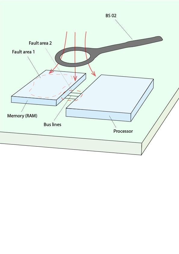
Figures 1 to 3 show an electronic circuit in which a processor controls a screen via HDMI. The processor is connected to a memory circuit (RAM) via bus lines (Figures 1-3) and continuously retrieves its program code from this circuit. The pulsing with a standard generator leads to the error pattern that the image content on the HDMI monitor freezes. The error can only be rectified by interrupting the power supply to the processor.
The first task is to reproduce the screen freezing error when the module is pulsed with field sources. The HDMI system (HDMI connector, cable, and monitor) is the first possible source of error to be considered. Troubleshooting begins with the BS 02 magnetic field source, the largest magnetic field source in the E1 set immunity development system. Alternatively, the BS 02-h from the H2/H3 field source set can be used in conjunction with a burst generator or the BS 02-h from the TS 23 set TroubleStar Development System for ESD / Burst. The BS 02 is guided over the module at a maximum distance of two centimeters (Figure 1). The possible confinement of the weak point corresponds approximately to the size of the field source head.
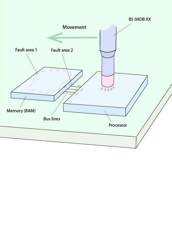
When the HDMI system is pulsed with the field source, image interference or a black screen occurs, but this does not correspond to the error pattern being searched for. The entire module is then exposed to the BS 02 field source section by section. In the area of the processor and RAM, the fault being searched for can actually be reproduced. With the higher resolution field source BS 04 DB (E1 set), the fault can be narrowed down further (Figure 2). Alternatively, BS 04DB-h from the field source sets H2 and H3 set can also be used in conjunction with a burst generator.
It is initially unclear whether the cause lies in the RAM, in the conductor lines, or in the processor. The pulsing of the surface of the memory circuit generates new error images on the monitor (similar to a checkerboard pattern), which are not relevant for the time being (see above).
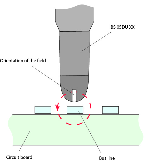
For further analysis, the area of the bus lines between the two ICs is examined with the BS 05 DU field source (Figure 3). Here the fault pattern can be reproduced directly on these lines. With this knowledge, suitable countermeasures can now be tested. To prevent interference on the bus lines, they must be shielded. As a test, the bus lines are therefore covered with copper foil and the module is pulsed with the standard generator again. The result is that the shielding prevents the corresponding error pattern. The successful shielding can now be put into practice with appropriate layout measures. For example, the bus lines could be laid in an inner layer and shielded with a ground layer.
Note: This immunity test should be carried out as early as possible in the development phase (first prototype) in order to avoid unnecessary layout changes. The targeted, strategic use of field sources provides developers with effective tools for identifying weak points in the design and then taking targeted countermeasures.
Use the following Langer EMV products for this purpose: