
The P1 set with the three mini burst field generators is used to quickly test the immunity of assemblies. They are a quick alternative to EMC test stations, where larger generators have to be set up and put into operation at a laboratory workstation, which is time-consuming. The pocket-sized mini burst field generators can be put into operation immediately without any additional measures. This enables fast, flexible testing of electronic systems. At their tip, they generate burst or ESD-like interference fields with an interference pulse of 2/8 ns. The mini burst field generators are guided by hand with their field-emitting tips close to the test object (e.g. printed circuit board). They are most effective when they are placed directly on the surface of the device under test.
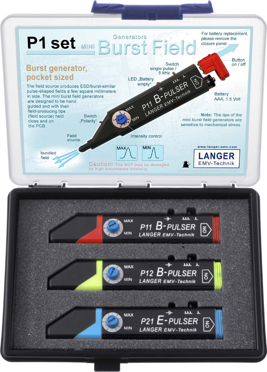
The weak points react to the pulse field and functional faults can be triggered. In the device under test, weak points can be found specifically on individual sections of the PCB design (faults in the ground system, individual conductor tracks or IC pins). The separation of magnetic (P11 and P12) and electrical (P21) coupling enables optimum adaptation of the EMC countermeasures to a weak point. Figure 1 shows the three generators (from the P1 set). Each of the generators fulfils a specific task.
- P11 Mini burst field generator generates a magnetic field that emerges axially from the tip. The magnetic field can be used to test current and signal loops in the module for interference immunity. It can also be coupled into the surface of ICs in order to hit the die of the IC.
- P12 Mini burst field generator generates a magnetic field that emerges in a circle from the tip. The magnetic field of this mini burst field generator can selectively detect IC pins and conductors and induce an interference voltage in them. The (sensitivity tester) P12 can be used to test the sensitivity of IC inputs and conductors.
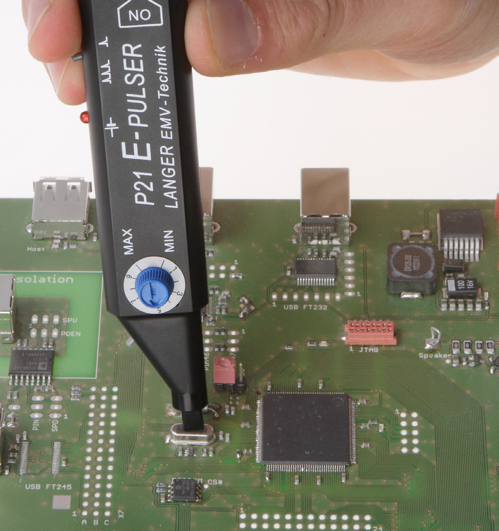
- P21 Mini burst field generator generates an axial electric field at its tip. The tip is shaped in such a way that the field electrode can be placed longitudinally on conductor runs for coupling. This enables intensive direct coupling. Active inputs of ICs (reset, clock) react particularly sensitively if they have high-impedance drivers (pull-up or pull-down resistors).
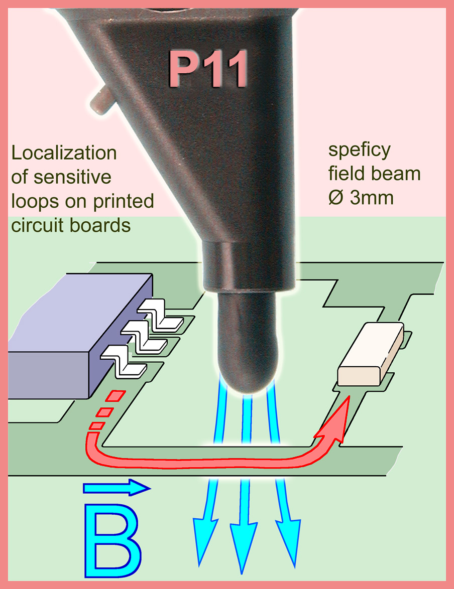

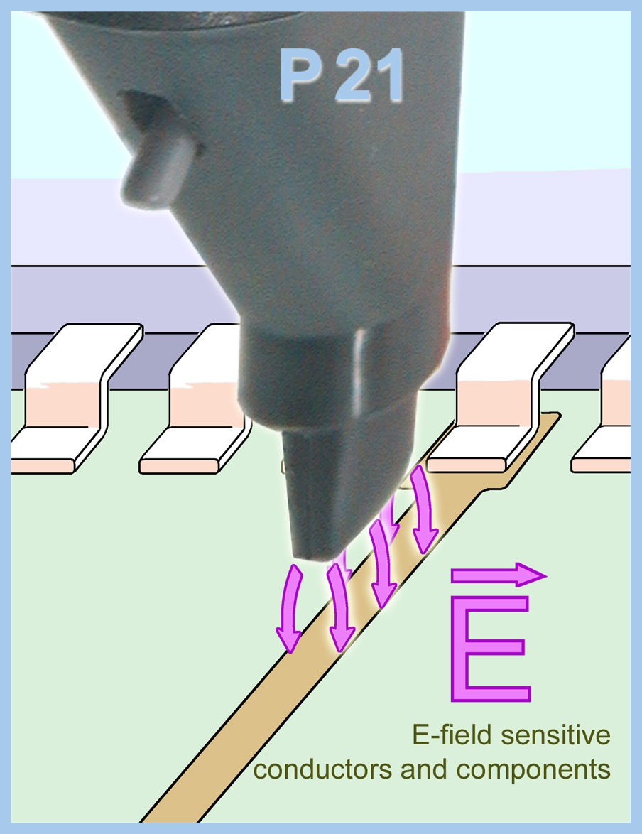
Figure 3 shows the use of the P12 pulser when interference current is coupled into a VDD/VSS capacitor of the microcontroller. The interference current can briefly reduce the supply voltage in the IC and switch off the IC for a few nanoseconds.
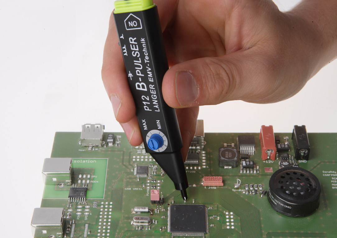
Figure 4 shows the application of the mini burst field generator P21 on a quartz oscillator. This demonstrates that the module can be disturbed via the quartz oscillator when exposed to an electric field. The mini burst field generators are used to analyze flat assemblies during development. The generator's field source generates ESD/burst-like pulsed fields limited to a few square millimetres. The adjustable intensity of the disturbance variable means that weak points can be compared with each other and the effectiveness of EMC measures can be checked. The separation of magnetic coupling (B-pulser P11, red) and electrical coupling (E-pulser P21, blue) enables magnetic and electrical weak points to be differentiated and the countermeasure corresponding to the cause-effect relationship (E/H) to be determined.